2014-07-10

First oil change

I kind of forgot to take more pictures since the last ones. There wouldn't be anything too special anyway.

I took my forks to the dealer for service since I haven't yet tried to do it myself, but considering the price, 200e, I think I'll try to do it myself next time. Looks like the work itself covers about 2/3 of the price and doesn't look like black magic so it would be worth the effort. I think I already have a pretty good idea where to pay attention and what's needed for the service.

The bike also got a new set of tyres, Metzeler Roadtech Z8s since the old ones wouldn't have lasted for the whole season (assuming the bike works for that long :)) and those had been just standing still for two years. Didn't notice myself but the guy at the shop told that the wheel bearings made a little bit noise when balancing so I replaced the wheel bearings along with the sprocket carrier ones. Finally put a new chain and sprockets and it was ready to run.

Funny how you start hearing completely new noises after completing this kind of project for the first time. I think most of it is that I didn't previously pay attention to. It seems to run pretty well and at least on the engine side, the bearing noise is totally absent. Clutch plates are new with the old basket so it doesn't make too much noise. I don't really hear anything extra when the bike is standing still and accelerating. When riding, there's probably some intake noise at higher speeds, so need to check the intake manifolds that they are tight. Or it could be completely normal, wouldn't worry too much.

So 1000 kilometers behind so far and I decided it's time for the first oil change. There was some debris on the oil plug which I was expecting too since there are gears that may be in a little bit different position, piston rings repositioned etc.


That's something magnetic and even though the picture doesn't clearly show, it's kind of shiny stuff. The amount isn't huge so probably nothing to worry about. The oil filter screen had just some flange sealant bits on it. Not too much though. I still plan to pull both side covers off and check that flywheel and primary drive gears are still intact.

2014-05-11

Alive, ALIVE!


The frame attached to the engine. I used two mates to attach it: lifting with two and the third one put the mounting bolts in. I also took the front fork for oil change and cleaning while it was easy to take off. Luckily I had quite a few photos since I almost struggled with cable/hose routings but got that all settled finally. Nothing too special to write about since it's mostly working with things I do on every ordinary maintenance.


Then I had to make some room to put the oil cooler, horns and the center stand on so I put the front wheel on and used a rear lifter.


And here it is, getting ready for the first start. The center stand bolts are still somewhere very safe since I couldn't find them. I wasn't as organized with those as with other parts that were all on labeled zip bags. Maybe they were in too bad condition and I threw those away? Well, I'll get new ones and borrowed the ones from the side stand this time, since they are the same size. I put the bike on the center stand for the first start since somehow it feels safer than the rear lifter. So here is the video:


2014-05-09

Almost a motorcycle

It's getting closer. I continued by lifting the frame away from the lift table so I get some room for the engine. There were two nuts left to tighten: The primary gear nut and flywheel nut. Both require significant amount of force so I didn't even try to do that when the engine was on the table.


 The primary gear nut is 190Nm and the flywheel nut is 270Nm. My biggest torque wrench can go only up to 210Nm and even though the book says the tolerance should be only 5% while generally they are 10%, it really shouldn't matter that much or at least that's what I heard from quite experienced technicians. I started by assembling the flywheel and tighten it just a bit so I can attacht the flywheel holder tool I bought earlier. I was told that I could just use impact gun to tighten the nut so there wouldn't be need for a tool, but I didn't feel very confident about that so I decided to get the tool. It's not the original type that attaches to the case with two bolts but instead it has a long handle so it requires two to hold it and tighten the nut which wasn't a problem since I share the garage with my friend. Holding the flywheel it was fairly easy to tighten the primary gear nut to 190Nm and bend the washer to lock it. On the flywheel side I just tightened the nut to wrench's maximum 210Nm and used an impact gun to tighten it about 10 degrees more. I think it's fine.


Once the covers were closed by applying sealant on the surfaces I attached the swingarm to the case and it was ready for the frame to be lifted on it.

Pistons, cylinders and heads


It was time to make the pistons shine since they were pretty dirty. Nothing was seriously burned so it was quite a bit easier than with the valves. Just some WD-40 and wiping. I figured it would be whole lot easier to fit the pistons in the cylinders first as opposed to attach them to conrods first even though those circlips tend to be a bit tricky sometimes to get in specially when theres not too much room. And that's the method the Workshop manual suggested as well. I had new seals and circlips but didn't see it necesary to replace the piston rings since they looked good and there was only 40k km on the bike. So a nice cleanup for pistons and the cylinder, a thin film of oil to cylinder pipes and with a help of piston ring compressors the piston slipped in to the cylinder.


The cylinder pipe gasket requires some flange sealant on both sides of it and I used the Loctite's product that was mentioned in the book and it was available in the local store. It was pink color so of course I had to choose the rags covering the intake holes accordingly! Then I inserted the cylinders, locked the pistons to conrods, inserted a new head gasket, the head and head nuts.


There are three torques for the head nuts: 15Nm, 30Nm and finally 48Nm. I had the self made tool and a digital torque wrench I invested on. I think the tool was worth spending some money since you can't break it by forgetting to untighten the spring and if we go by the book, you should loosen and retighten it between every nut. This one doesn't require any of it and it also shows the current torque, so it was quite convenient to tighten the bolts evenly (and of course working diagonally). The nuts and stud threads were greased before tightening as the book suggested and without greasing they would be looser due to friction.


Once the heads were tight it was time to assemble the oil pump and the timing belts. Oil pump should be filled with oil to avoid air lock in which case the oil wouldn't flow when the engine is started. Also I had all new o-rings for the pump. Horizontal cylinder to TDC by looking at the marks on the other side of the engine (timing gear and the gear on the crankshaft under the flywheel) and the mark on the pulley on the RH side. Then align the camshaft pulleys to their reference marks and put the belts on. I used my mobile phone guitar tuner app to tighten the belts to 110Hz.


Gearshift lever alignment

Before assembling the cylinders and heads I took some time to make sure the gears engage correctly. For that the gear shift lever/fork needs to be in place. Ducati Workshop Manual mentions a special tool for the alignment and of course I didn't have one. But I don't see why it would be necessary since the only thing it does is 1) lock the gear selector drum in place and 2) shows the mid line of two drum rollers. The gearbox should be on second gear when it's aligned so if I had been wise enough and figured it out before closing the cases I would have marked the mid line of those two drum rollers with a marker. In fact this could have been done on the factory so the tool wouldn't be needed. When the bike is on the second gear, the drum won't move by itself. And all you need to do is to align the mid line of the two drum rollers and the line on the gear shift lever fork. The goal is to obtain approximately the same amount of movement to both upshift and downshift and then tighten the bolts. It's hard to get accurate feeling without using the actual shifter with your foot, but luckily this is fairly simple to adjust afterwards if needed. Of course the oil needs to be drained and LH side cover taken off..


2014-04-12

Case closed!

Once the heads were done, I got the new 0,05mm smaller shim for the crank so it was time to prepare to close the cases. I had photos of the opening ceremony which showed pretty well how everything was in their places. All the books that I have mention to start the reassembly by building the LH side case. I tried to think a reason why since most of the case joining bolts are on the other side so one would need to close the case and flip it over and then tighten the bolts. If I had a rotating engine mount it wouldn't be a big deal but on a table it's quite hard to rotate so I was rebel and installed the parts on the RH side case. There's one rubber O-ring inside which has a seating hole on the LH side case so that would be the only possible challenge as you want it to seat properly. Just a very small amount of grease was enough to glue it to the hole and it didn't drop off while I put the LH side case on.

Here it is waiting for sealant and closing. It's important to run through all the gears to check every gear engages. It will not happen very smoothly because there's a lot of play withou the other half of the case. Then a careful cleanup of the surfaces and we are ready to go. I used Ducati branded ThreeBond since it was available in the shop I ordered the replacement parts from and wasn't realy very expensive. I suppose you can get some cheaper permatex stuff and I heard the Permatex black would be great but since I really don't have any personal experience, I just went with Ducati recommendation.


Applied quite thin but consistend layer of the sealant and closed the case. Then tightened the mounting bolts working diagonally starting from inside M8 bolts. There are two torques for the book marked as 1st torque and 2nd torque. Not completely sure how this should be understood because I can think of two possibilities: 1) to torque everything to the first torque and then to second or 2) torque everything to the first torque, let the sealant to dry and then torque to second. Well, I followed the first thought and I suppose time will tell whether the oil stays in or comes out. The sealant mostly fills the gaps of the surface so I suppose if it was crucial, at least one of the books had mentioned about it. I let the sealant dry for a day before continuing with the reassembly.

Cleaning and lapping

There was quite a thick layer of carbon on the valve faces which was very hard to clean up without removing the valves. I also realized it's probably best to reseat them too so I removed them once again.


On the left there's the one that I cleaned valves in place and how they looked like before. The intake valves got pretty shiny but the exhaust valves still are a bit dark. The surface is smooth and all the carbon is removed but didn't manage to polish those as well as the ones in the other head. So I removed them from the heads, attached to a drill with a piece of plastic tube to protect the valve and run them against a scotch brite pad lubricated with WD-40. On the right side you can see the results: Both intake and exhaust valves are bright and shiny but it didn't come easy, specially for exhaust valves. I probably spent half an hour for exhaust valves to get the carbon off while intakes started to shine in half of that time. Well, they are clean now even though the same treatment didn't make exhausts very bright on the other head. They are clean and carbonless still.


For reseating I used fine valve grinding paste and a manual tool. The contact surfaces had some carbon dots on those but they disappeared in the process. I ran a brief leakage test by pouring some alcohol on the head and visually inspecting the intake and exhaust channels and saw only one very small leakage on vertical exhaust valve. I think it took 10 minutes to show up but since the valves were still unattached to the rocker arms it was easy to just reseat once again. I ended up using coarse grinding paste this time first and then some fine again and I think I got it seated so the leak was finally gone.

2014-04-04

Valve adjustments

One picture tells more than a thousand words, right? So here we go:


That's my notes of measuring, adjusting and measuring and probably not very useful for anyone else than me. So I made a sheet that's divided on horizontal intake, horizontal exhaust, vertical intake, vertical exhaust and those are divided in chain side (left) and belt side (right) and again divided in closer and opener. There are ready made templates all around on the internet but I used my own which took only couple minutes to draw with google docs.

The valves weren't way off, depending which spec you follow. Vertical intake left closer was .008 inch and that was the biggest clearance there was. I still did some fine tuning and even ended up changing couple bits but that's all. I decided I'll follow LT Snyder's specs and not to worry too much for less than .001 differences except when the gap is smaller than LT or Ducati spec. More experienced guys always tell they used to fine tune by sanding shims down to get exactly when they were young but stopped worrying too much when they gained some experience. So I guess the settings I got as a result are decent:


Horizontal intakeHorizontal intakeHorizontal exhaustHorizontal exhaust
Left opener
.0055
(no adjustment)
Right opener
.004
(tight, sanded down a bit)
Left opener
.007
(a bit tight, no adjustment)
Right opener
.007
(was .004, changed shim)
Left closer
.004
(was ~ .0025)
Right closer
.0045
(was .003)
Left closer
.004
(bit tight, but was .003)
Right closer
.004
(was .003)

Vertical intakeVertical intakeVertical exhaustVertical exhaust
Left opener
.0045
(no adjustment)
Right opener
.004
(sanded down, was .0035)
Left opener
.0065
(no adjustment)
Right opener
.006
(was .0055, sanded down)
Left closer
.005
(was .008, changed shim)
Right closer
.005
(no adjustment)
Left closer
.0045
(bit loose, no adjustment)
Right closer
.004
(no adjustment)
LT's specs are bit tighter at some places and in some places they fit in Ducati's spec. LT says:

Intake opener: .004
Intake closer: .004

Exhaust opener: .006
Exhaust closer: .004

The Ducati spec in the LT's book isn't the same as in my Workshop manuals so I didn't write down those here, but the basic idea is that too small clearance is as bad as too big. There has to be clearance or the surfaces won't get lubricated. I would guess that big clearance on intake opener side could cause backfire but generally it's probably to avoid hammering the shim/valve with rocker arm.

The job is quite easy when you have the heads on the table. However pressing the rocker arm to get loaded gap is tricky with traditional way (pushing with screwdriver or small socket) so I took couple old screwdrivers and bent them so I was able to close the closer gap from between the back side of the rocker arm and the clinder head:


Those MotionPro tappet feeler gauges are really must have as it's so much easier to measure than with traditional ones. There are couple sizes missing. I'd like to have .007, .010 and perhaps .011 or so. Of course one could use .008 and .002 together and so on since I have two sets, but it's a bit tricky to get accurate measurement that way.

Once I got the inspection covers cleaned and all the bolts tightened, I realized it would have been handy to clean the valves while they are unlocked. Of course I realized it afterwards so I guess I have to remove every valve once again. Well, still don't have the shim for the crank so I nothing else to do meanwhile :)

Not dead yet, crank shimming measurement

The project has been on hibernate since it looked like I won't be able to make it on the last season. I've been doing other stuff on the winter so this one had to wait but now the sun starts to shine again, but luckily it's not too warm yet so maybe I won't get too late start for the season. I have other bikes too but I really really would like to start it with this one.

So continuing from where I left on the fall. I had new bearings in the cases and I needed to determine the required shimms for the crankshaft to obtain the desired preload. The shims were 2,25 mm on the chain(LH) side and 
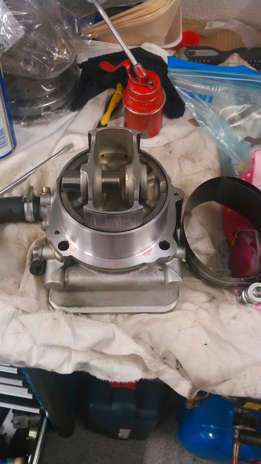
2,15 mm on the clutch(RH) side. But the mains went bad so it made me wonder what's wrong. I actually measured the end float on the fall and came in to conclusion that the preload was actually correct. But I still decided to take a second look now as I'm continuing the project. Found out something new I hadn't noticed before: crankshaft's oilway plug was loose and its thread prevents crankshaft's shimm to align nicely. It actually causes inequal load to the bearing so this could actually be the reason why the main bearing looked like it did. Here is a picture:


I went through my older photos and noticed it's loose in there too. I swear I didn't untighten it and the photos confirm that. The plug even had some scratch marks on it. The shim itself was just polished compared to the one on the other side. Anyway the plug should have thread locker and it should be tightened to fully home. It didn't seem to have anything extra in the thread. It's tight now and thread locked so probably not an issue anymore.

Next the actual measurement. There are two methods in the Workshop manual: the first one is to measure the depth of both cases and the thickness of the crank from web to web and add the preload. I had my doubts because while this should be perfectly good method to measure it requires more precise tools that are on my disposal. So I decided to try out what kind of numbers I'll get using a level and a digital caliper:


The crank isn't any issue since it gives quite consistent readings. The case is a different story. The level is pretty much the best straight item I have but doesn't seem to be good enough. The idea is to measure the distance between the contact surface on the case and the bearing. The readings I got varied for about 0,15mm to 0,20mm so that's way too inaccurate. I didn't even threw out the notes of the measurements but at least I know I can't do it this way. There's one thing this method revealed though: LH side is a little bit wider than the RH side. That may be the reason why the original shims aren't equal size.

The easier way is to get thinnest shims there is and put the crankshaft in and close the cases and tightened the screws to specified torque. So I got a pair of 1,90 mm ones (damn 25€ each) and measured the end float with dial gauge:


Even with this setup the numbers aren't obvious to me. They probably are for someone who has more experience but there's always the first time. So I had the dial gauge at the end of the crankshaft. Then I rotated the crank for a few rounds and the dial still pointed zero, so all good. The book says to use a screwdriver to level the crank up but I found the readings to have more variation that way so I just grabbed the crank with hands from the top and pushed from the botton, and got pretty much only 0,01 mm differences. I came in to conclusion the end float with 1,90 mm shims is 0,25 mm.

I have two versions of Workshop manuals: 2001 and 2002. The newer one suggests a preload of 0,30 mm and the older one 0,15 mm ± 0,20 mm. I think I'm gonna trust a bit more to the newer one of 0,30 mm. It also fits to the older specification which goes up to 0,35 mm preload. So my case:

1,90 mm + 1,90 mm + 0,30 mm (preload) + 0,25 mm (measured end float) = 4,35mm

So I need 4,35 mm of total shimming. What I had was 2,25 mm + 2,15 mm = 4,40 mm. This means a preload of 0,35 mm which may or may not be a bit too tight. It's in older spec but I kind of would like to avoid the limits of the range so I ended up ordering one 2,20mm shim for the LH side. While I wait for the shim to arrive, I can do the valves.